
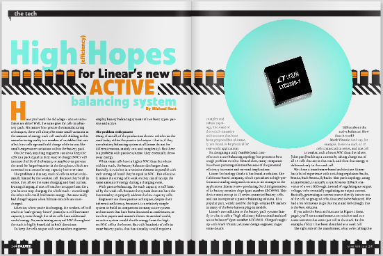
Linear’s new addition to the battery pack systems family is what it calls a “high efficiency bidirectional multicell active balancer” (part number LTC3300).
Have you heard the old adage – no two snowflakes are alike? Well, the same goes for cells in a battery pack. No matter how precise the manufacturing techniques, there will always be some small variation in the amount of energy each cell can hold. Adding to this manufacturing reality is a number of variables that can affect how cells age and hold charge while in use, like small temperature variations within the battery pack. On the road, anything engineers can do to keep the cells in a pack equal in their state of charge (SOC) will increase the life of the battery, or maybe even prevent the need for larger batteries in the first place, which are oversized to account for any capacity loss over time.
The problem is that any stack of cells in series is ultimately limited by the weakest cell. Because they’re all in series, they all see the same charging and load current. During charging, if one cell reaches its upper limit first, you have to stop charging the whole stack – even though the other cells could hold more energy – because really bad things happen when lithium-ion cells are overcharged.
Likewise, when you’re discharging, the weakest cell will reach its “can’t-go-any-lower” point (or it will lose more capacity), even though the other cells have additional useful energy. So, maintaining an equal SOC throughout the stack is highly beneficial in both directions.
To keep the cells on par with one another, engineers employ battery balancing systems of two basic types: passive and active.

The problem with passive
Many, if not all, of the production electric vehicles on the road today utilize the passive technique – that is, if they use a battery balancing system at all (some do not for different reasons, mainly cost and complexity). But there is a problem with passive systems: They essentially throw away energy.
When some cells have a higher SOC than the others within a stack, the battery balancer discharges them. Basically, it switches in a resistive element in parallel with each strong cell until they’re equal in SOC. This effectively makes the strong cells weak so they can all accept the same amount of energy during a charging event.
With passive balancing, the stack capacity is still limited by the weak cell, because the system does not have the functionality to properly address the low-capacity cells.
Engineers use these passive techniques, despite their inherent inefficiency, because it is a relatively simple system to build in comparison to many active system architectures that have been discussed at conferences, or in white papers and master’s theses. In an ideal world, an active system would shuttle energy from the highest SOC cell to the lowest. But with hundreds of cells in some battery packs, that functionality would require a complex and robust topology, like some of the switch-intensive architectures that have been proposed but ultimately not found to be practical for real-world applications.
So, designing a truly feasible (read: cost-effective) active balancing topology has proven to be a tough problem to solve. Nonetheless, many companies have been pursuing solutions because of the potential efficiency increases and on-road implications.
Linear Technology thinks it has found a solution. The California-based company, which specializes in high-performance analog integrated circuits, is no stranger to the application. Linear is now producing the third generation of its battery monitor chips (part number LTC6804). This device monitors up to 12 series-connected battery cells, and can incorporate a passive balancing solution. It’s a popular part, widely used by the high-volume EV makers in many of the best-known plug-in models.
Linear’s new addition to the battery pack systems family is what it calls a “high efficiency bidirectional multicell active balancer” (part number LTC3300). Charged caught up with Mark Vitunic, a Linear design engineer, to get some details.
Tell us about the active balancer. How does it work?
Mark Vitunic: Let’s say, for example, there is a stack of 12 cells connected in series, and one cell is weaker, with a lower SOC than the others. [This part] builds up a current by taking charge out of all 12 cells that are in that stack, and then that energy is delivered only to the weak cell.
We chose a transformer-based architecture. Linear has a lot of experience with switching regulators: bucks, boosts, buck-boosts, flybacks. This part’s topology, using a transformer, is actually a synchronous flyback converter of a sort. Although, instead of regulating an output voltage, we’re essentially regulating an output current. Basically, generating a current source directly into or out of the cell, or group of cells, that need to be balanced. We had a lot of reasons to go this route and feel strongly this is the best solution.
If you take the basic architecture in Figure 1 (next page), you’ll see a transformer, two switches and two sense resistors that exists per cell in the stack. In this example, CELL 1 has been identified as a weak cell.

The right side of the transformer, what we’re calling the primary, is essentially connected in parallel with CELL 1. The secondary side of the transformer, the left side, reaches all the way to CELL 12. The secondary of the transformer will build up a current by taking charge out of all 12 cells that are in that loop, and then when it commutates over to the primary that energy is delivered only to CELL 1.
If you have a weak cell, we think it’s better to give it some help from its local neighbors. You’ve brought them down a little bit, but now the average capacity of that group is much closer to something reasonable.
In this solution you’re actually removing a small amount of charge from the weak cells before you put a lot of energy back into them. You can think of it as taking charge Q out of 12 cells, and putting 12Q back into one of them (minus some efficiency losses that are less than 10 percent). I’m not saying that’s a negative on the part, which will be a reality in most any solution. What it means is that we want to have the secondary winding across as many cells as possible. In this example it’s across 12, but if you used a higher-voltage switch on the secondary, you could reach beyond that. It’s just limited by the breakdown voltage of the FETs that are used. Twelve is a convenient number because that works out to about 48 V on a 12-cell stack, and you can probably get away with 60 V FETs, which are common and fairly priced. Architecturally, there is nothing limiting you from having that charge come from a larger group than 12.
The solution is scalable to pretty much any balance current or battery capacity size, because you select the external components for the number of cells you’re going to have in the secondary. And you choose the sense resistors for the balance current that you want. Then the chip does all the controlling.
What is the cost of implementing your active system?
MV: In terms of cost per cell, we think our solution cost – which includes all of the external components required – is in the two to three dollars per cell range. That’s independent of the cells’ capacity or the balance current that you want to run at. That would be the cost of all of the external components per cell, plus one-sixth the price of this particular chip (because you need one chip to interface with every six cells).
You can certainly use this for low-capacity cells, but we think the cost would not be ideally targeted for that. This makes more sense with bigger cells, in the area of 40 amp-hours. That’s not a hard number, just an estimate.
The alternatives are either no balancing at all or passive balancing. In those cases, if you want to maintain the same driving range and battery life as a high-efficiency active system, you can either buy bigger cells with a higher amp-hour rating – a huge incremental cost – or you give up performance, which nobody wants to do.
What is the efficiency of the energy transfer?
 MV: It is somewhere in the low 90 percent area at the power stage, and the efficiency doesn’t vary much with the number of cells you put in the stack. With the flyback architecture, we sized the transformer to not run at duty cycle extremes.
If you look at Figure 2, here we’re comparing another active balancing architecture with 80 percent efficiency. Our solution, at around 90 percent, may sound like a small improvement if you look only at efficiency. If you look at it in terms of loss – meaning how much heat is generated around the batteries in order to shuttle charge around – now comparing 80 and 90 is really comparing a 20 percent heat generation to 10 percent heat generation. The architecture we chose essentially doubles the amount of current that you can balance cells with. So, the net result of this is that you get less heat and faster balancing.
Passive balancing is not even shown on this curve because essentially the efficiency is zero percent. You’re not moving any charge to a cell that could use it; you’re just burning it up as heat.
What’s also important is not just how efficiently you move the charge but how efficient the algorithm is. Because a portion of the charge that is being redistributed is coming from the low-SOC cell itself, a part of the overall efficiency is algorithm-dependent. We think this architecture is much friendlier in that regard as well, because we can reach across a lot of cells when we’re sharing charge.
Why did you choose a solution that balances locally instead of across the whole pack?
MV: Take for example a stack of 100 cells, which would have a 400 V common mode difference between the top cell and the bottom cell. Any architecture that would attempt to move charge from the bottom to the top would need components that could hold off 400 V. It’s just not practical. It makes far more sense to locally redistribute that charge to a subgroup of cells, like a module of 10 or 12 cells, for example. You can address the problem cells much more efficiently that way.
To take charge off just the highest cell and move it to the lowest cell would require a switch network that basically connects every cell to every other cell. If you had a stack that was 50 or 100 cells high, that would be very cost-prohibitive and basically an unworkable number of switches. It’s not practical or necessary to be able to move charge from one cell in a group of 100 to any other one cell. We need two switches per cell and can distribute charge over a large group, so we believe this architecture is very advantageous.
When does the cell balancing occur – during charging, discharging, and/or at rest?
MV: It can happen during load or during charging of the stack, it doesn’t matter. That being said, for the chip that is monitoring the voltage of the cells, and possibly the temperature, sometimes it may be beneficial during that measurement to pause activity of the stack and take a quieter voltage reading. That’s not required, but people tend to do it. When balancing at very high currents, pushing 5 amps back and forth between different cells, you might want to halt that for a brief period to take a voltage reading, recalculate the state of charge, and then resume balancing. When people are moving that much current around in a system they like to get constant updates on what the cells are doing, so that if anything is wrong it can be addressed quickly.
How soon can we expect to see the first systems on the road?
MV: This chip was officially released on March 5, and there will be a learning curve for people to understand how this part works. I think people are starting to believe that they need active balancing, because they’re seeing how they’re limited with passive or no balancing at all. So, now they’re trying to understand the cost and what the actual benefits are.
If it’s an automotive application, the cycle to get something designed in is longer, usually years, not quarters. Small applications I think will be sooner. We’ve been working with all the major players in terms of providing sample parts and demo boards. But all I can say really is that the part is now on the market and available for sale.

This article originally appeared in Charged Issue 7 – MAR/APR 2013